Monday, July 15, 2013

Before picture

Repacking a stuffing box (packing gland)


Vessel: 1979 Newport 30MKII
Engine: Universal Diesel 18hp (5216?)
Gearbox: 2:1 ration
Propeller shaft: 7/8"


Intro

This is just to share some interesting lessons learned that might apply to similar set ups or sister boats. For general instructions on how to do this please see.
http://www.pbase.com/mainecruising/stuffing_box

Disclosure: what follow is for information purpose only. What you do with your boat is your responsibility. Some have reported significant amount of water flowing in once the stuffing nut is removed so it is your responsibility to make the right decisions before attempting any project.

Tips and tricks

After picture (wet due to cleaning)
  • In my case the stuffing box body was tight enough around the shaft that the leak was minimal after I removed the packing nut.  So I did my job with the boat in the water. The water flow increased over several minutes but it was still well within what a bilge pump or manual pump can handle.
  • I used narrow pipe wrenches. In my case the two nuts measured 45mm and 50mm. Big, crude plumber wrenches might not work well. Look for something sturdy but narrow that can properly grab the nuts.. I used RIDGID E-110 Hex Wrench. Just FYI.
  • The packing material for my stuffing box was 1/4" Flex. 
  • The packing gland in my case is so close to the gearbox that you can barely unscrew the stuffing nut and move it away from the rest of the packing gland so you can work on it. Be prepared and check yours before you start
  • to remove the old packing, that is hard as a rock initially, I used a long wood screw. I carefully thread it into the stuffing for about 5 full rotations and then gently wiggled it back out. Do make sure to stay away from the shaft, you do not want to scratch it! Same for the stuffing nut albeit it is less critical. It worked like a charm and cut my time in half once I realized I could do that. I pulled the first of three stuffing sections using a picker and it took for ever since the only way to really get it out is to carefully find the splicing point and use that as leverage. Using the screw method above it is straightforward and considerably faster, just align the screw with the shaft so not to touch it and go.
  • Once I put it all back together with new packing, I hand tight it and left it soaking overnight. There were no leaks already. The next day I unscrewed it until I saw water dripping, then slowing tighten it until the leak stopped. Secured the counter nut, started the engine and tested that it drips every 30 sec or so. Ditto, done.

Monday, April 1, 2013

Porsche Boxster M96 engine: Intermediate Shaft Bearing replacement

In a nutsheel

  • 2003 Boxster, 2.7l M96 engine, stock
  • 91K miles
  • oil drip started a number of weeks prior to service
  • ~1sec rattling noise at start up started at about the same time as above and became more and more frequent up to occurring at every engine start
  • no other signs of problem
  • Not to give away the ending but this is a happy ending story
  • Not a DIY project for beginners, or even intermediate IMHO

Intro

There are a ton of blog posts about this, I am not going to replace them or repeat any of them. The purpose of this blog is to share some information I did not see anywhere else and to share some photos so you know what to expect. The best way for you to start is actually pelicanparts.com then come back here for some tips from a DIY who has done it...successfully.

A word of caution: I am sharing this information for your knowledge.  Quite frankly, I advice against doing this yourself since the risk of destroying the engine by accidentally skipping the timing chains is very much real.  As they say...

Do not try this at home. 

FYI: I rebuilt my first engine at 14, I can do most regular maintenance on my cars blindfolded. My dad has a mechanical engineering degree and though me a ton about cars before I could walk. I have two degrees in engineering and I have been working on engines for decades as DIY. Even at that I took a calculated risk and I quadruple checked the cam alignment to the level of paranoia since a mistake in this project is very, VERY expensive. Again, do not try this at home. 

Ok, I am done with the disclaimer.

Tip 1

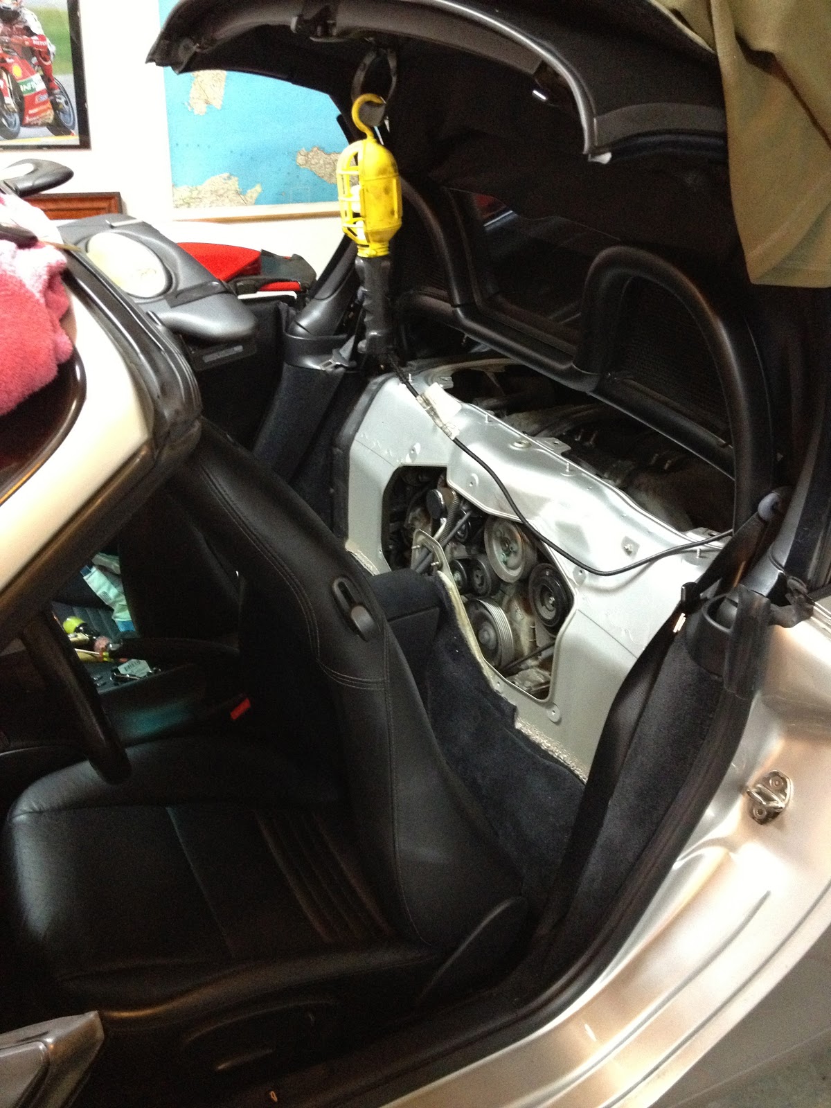
If your engine is dripping slowly from the place where the transmission meet the engine and/or if you hear a gentle rattling sound at start up that lasts about a 1 second, you might have my very same condition and you should have your car serviced. In my case the bearing seal clearly gave up and the high temperature grease of the sealed unit was completely gone and replaced by engine oil. I am convinced that this bearing was on its way to self destruct, I caught it just at the beginning of the process. For the record, oil should not be present inside this bearing since when this happens, the oil is basically trapped inside the bearing and it will slowly collect debris and start wearing all moving parts. It is a slow process but it will eventually result in the bearing failure and, judging from the increase in frequency of the noise above mentioned, the degrade accelerates exponentially once it starts. I bet if I waited another few weeks, this would have sounded (and looked) much worse. This unit was starting to show signs of excessive play once I removed it but, again, I did catch it in time so I had no damage. As you can see from the photo, it clearly has oil in it (seal removed) so I was sitting on a time bomb. Lastly, the noise at start up is gone. I suspect it was coming from the balls skipping and sliding in the races until they caught up with the RPM of the engine.

Tip 2

Take your time if you DIY and put every nut/bolt back where it come from loosely as you remove a part. It might be time consuming but it makes reassembly a stress free ride. I used this tip for the big bolts connecting the transmission to the engine. Not only they ARE different from one another, at some point Porsche changed what bolt was used in what hole so your engine will likely be different than some of the blog posts out there. In my case it looked like one bolt was missing. In reality, my car was assembled in the factory with different bigger bolts but they also decided to use one less than the first generation engines. Do not panic, just mark them clockwise (that is how I did it) and just put them aside. I used the triple square on the bottom left as my n.1, then went clock wise and marked each hole and each bolt with a marker and then I moved to the transmission removal step (not covered here). Here are some shots of the work in progress. It also shows the IMS cover after the replacement with T-Curil and the new sealed bolts. That takes me to the next tip.

Tip 3

Do use new bolts on IMS cover, on the pressure plate and on the flywheel. I forgot to buy the latter and de facto I had to stall my project for a few days. Learn from my mistake! In general, make sure you order everything you need ahead of time. Do not short cut, follow the instructions from a proper service document and replace everything they say to replace. This is the mechanical systems that grabs the 225Hp from the engine and transfers it to the rear wheels. It is not the right place to be on the cheap IMHO.


 Tip 4

I have read that both Porsche and the Bentley service book say that after you torque the flywheel bolts, that each need to be turn an additional 90 or 120 degrees (Bentley say the latter). I used the fact that the bolts stars have 6 tips (see close up of the inside of the bolt) so I market the position of one tip WRT the flywheel after I torqued them, then marked two tips counter clock wise from it. Then I turned the bolts as close as having the two marks meet. I did not stress about doing exactly 120 degrees since I did the process by hand and I could tell when I was getting to a similar amount of effort required to rotate them. So effectively I stretched them at least 90 but not more than 120 degrees. Again, I have driven the car several hundred miles since, for what is worth. BTW Obviously you need to use a flywheel lock when doing this, look it up.


 Tip 5

Do buy a clutch alignment tool, it makes life incredibly easy during re-assembly and it is the cheaper tool you will need to buy for this project!
 

Tip 6 

Do replace the clutch while you are in there. Not only it is a smart thing to do, it will also give you a brand new car: my original clutch was considerably harder and more difficult to manage than the new one. In the nearly ten year since the car was built they redesigned the pressure plate (despite looking identical to the old one) and it works incredibly better! It is like driving a new car.


Tip 7

Manual transmission cables do pop from their ball pins. Just be gentle and apply even amount of force on both sides of the connector and they will pop. Disconnecting and reconnecting these cables is incredibly easy. DO make sure you memorize which cable goes where. They have different length so it is straightforward but do pay attention so you do not panic during re-assembly.

Tip 8

Last but not least, I took a simple approach during disassemble: keep all the parts that came from the left side on the left side of the "pile", conversely for the right side. This way I ended up with parts lined up next to the car on either side and it was a breeze to put them back. Things like the transmission mounts (which BTW double as engine mounts so DO support the engine with floor jacks) are symmetrical. Albeit they are clearly labeled with instruction as to which side they go, I still enjoyed the approach and made the process safe and effective. Not to mention that keeping things organized methodically will let you sleep better at night and it will lower your hearth rate when you finish the job and drive the car for the first time ;-)


Tools I used (it might help you create your project list)

  • full set of Torx
  • full set of metric sockets
  • full set of metric hex
  • M10 triple square, if you do not know what it is, look it up, it is educational
  • clutch alignment tool
  • a 32mm socket to remove/loosen the chain tensioners
  • a filter cover removal tool, hands or one-size-fits-all will not work!
  • lots of WD40 to clean and lubricate all the bolts/nuts prior to loosening them. Remember you are working on parts that have been untouched for years, be gentle and let the loosening agent do its thing
  • a breaker bar socket wrench
  • a couple of torque wrenches of different size


Saturday, December 8, 2012

2003 Porsche Boxster alternator replacement

Problem: Voltage drop when engine running. Normally the alternator should feed 13 - 14.7 Volts to the battery. Mine was at 13V when I first diagnosed the problem and then went to 12.3V (basically nothing atop the battery itself). In my case I also experienced one short light of the battery light on the dashboard. Most likely this is when the voltage regulator died.

Solution: the voltage regulator is likely the culprit. You can read a lot more here http://www.pelicanparts.com/techarticles/Boxster_Tech/82-ELEC-Alternator/82-ELEC-Alternator.htm
I ended up replacing the whole alternator with a rebuild one but if time is not of the essence you can order the voltage regulator from Pelican Parts and save about $100 (a re-manufactured alternator should run you about $170, if you are paying more you are probably being ripped off since the VR costs about $36 retail). From what I have read it is a good idea to just put a fresh rebuild alternator instead of changing only the VR but I will leave to your taste.


Tips and trick not available elsewhere:
- in a 2003 and likely older model Boxster/Cayman there is no point in disconnecting the engine lead cable in the engine bay as described in most how-to blogs (i.e. the link above). The wire has been modified into a Y-split and the third leg of the Y is still connected after you disconnect from the engine bay so you still have no gained any more mobility when working on the alternator connections. Just be careful when you do remove it and install it and leave this lead alone.
- it is a real pain to re-align the new alternator bolts, I used a strap to lift some of the weight of the alternator from the top so that it would move and rotate in place more easily.
- you will likely have all kind of problems getting the right hand side bolt to thread. In my case the alignment was a left to right issue more than a vertical matter (it will make sense once you do it, just check for it when it is time) and I had to push it towards the center of the car to make the holes to align.
- The right hand side bolt actually double as a pivot point for the alternator (sort of) and I tried install it with the left bolt in place and just "hook it" from the top into the grove built in on the engine blick but you basically have no visual to align it so it is a one in a million shot (look at said groove after you remove the old one, you will know what I mean). I used the technique above instead.

Monday, January 3, 2011

LED turn signal upgrade on motorcycle (Ducati S4RS)

This shows you how to upgrade your bulb turn signals with LED aftermarket ones. In my case I picked some short arrow shaped ones and in the process, I changed the tail cover of my motorcycle. First let's talk electrical circuit. What applies to everybody here is the fact that you need to restore the circuit wattage since LED consume considerable less power than bulbs. In my case the Ducati S4RS does not expose the relay that controls the turn signals so there was no option to simply replace the relay with one appropriate for LEDs. In my case the individual turn signal would go from 10 watt for the bulb based to 0.7 watt for the LED based. For all practical purpose I ignored the 0.7 watt and just computed how much Ohm do I need to replace the 10 watt. Using the Ohm law it worked out to 10 watt, 10 Ohm.

my DIY version


ready made and sold by MonsterParts.com

http://www.monsterparts.com/p/EE033H/LED+Resistor+Kit.html


Radio Shack happens to sell exactly those spec. You will need one per bulb ou replace. Some soldering, wired and shrink plastic tubing it is all you need to package it neatly. Add a couple connectors, actually make it into a bypass and you are done. If you are not the DIY type, I suggest mosterparts.com, they have this very same set up ready to go.

Aside: the resistors for the front.

The resistors for the front needs some special attention since they will be exposed to the elements. So I am creating an overlap on the top and folding it onto itself to create a sealed end. Installing this vertically with the sealed end on the top (wires exits from the bottom) will ensure that no water or moisture can get inside.

The rear

Note: the resistor in this case fit into a nearly sealed compartment inside the CF tail along with all the wire connectors. So this installation is a little easier since there is no concern of the electrical component being exposed to the elements.

The rear turn signals are installed by connecting them together using a rubber hose and clamping them between the tail light assembly and the license plate frame. Cutting a small opening in the middle of the hose will allow the wires to come out. The whole assembly results in a solid rubber mount that is reminiscent with pretty much anything on this bike since pretty much everything other than the handlebar is rubber mounted.

The front

Here are the DIY CF braces to install the LED turn signals on the front of the bike. These were made using a 1'X1' CF tubing cut with a Dremel. I used card board to mock up the part and to get a template for the holes. Just measure twice and cut/drill once ;-)


The final installation


Tuesday, November 30, 2010

Monster (S4RS) inexpensive tail mod and cleanup

The Ducati Monster up to 2008 are notorious for having a somewhat ugly rear fender and tail. In fact it is so unappealing that the tail of the bike is lovingly referred to as the "beer tray".
So I have decided to make a small and inexpensive modification by removing the extra plastic license plate holder and fender and using a couple of anodized aluminum strips to put the license plate right under its light, thus cleaning the tail of the bike quite a lot. The mod is somewhat self explanatory if you look at the pictures.

Before

After, close up
After from afar


Monday, October 18, 2010

Replacing front tire of my S4RS

Replacing the front tire is not that hard if you have basic mechanic skills. Do recall you need to remove and securely hold aside the brake calipers before you can remove the wheel. Other than that it is a straightforward matter.
1 loosen the axle bolt and remove the nut along with the spacer
2 loosen the four clamping screws at the bottom of both legs
3 remove and secure the brake calipers to the frame (see photo with the wheel off, can you see where I tie the caliper?)
4 gently tap the axle out, I used a small plastic handle from an old screwdriver and a rubber mallet
5 grab and make a note of the two spacers on each side of the wheel, they are different!

That's it. Note that the spacers are different in width and they can only be installed one way. If you swap them accidentally, the calipers bolts on the right side will not line up and you have to start over. Don't ask me how I know ;-)
Lastly, clean the axle and grease it before you put it back on. Same for all screws aforementioned. Look up the torque settings for all of them, several people have posted them on the web. If you do not know what torque settings are or you think you can just wing it, please take your bike to a dealership :-)